


|
|
|
|
Picture |
Date |
Description |
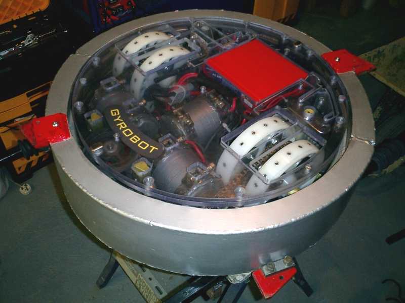 |
17/04/03 | Here are those wheels fitted. |
|
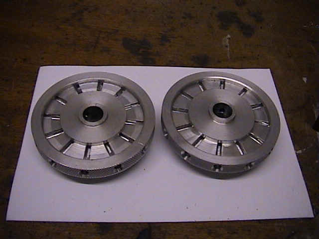
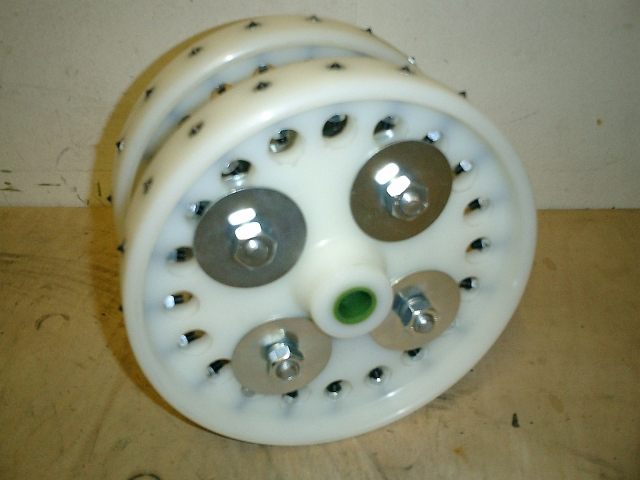
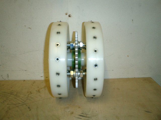
01/04/03 | Been a bit quiet over the winter period, just had our second child (well wifey has). Now it's nose to the grindstone again and back to play. Here we have a new tough lightweight design for the drive wheels. These have been studded with hardened spikes to give great traction the the wooden arena floor. Should be able to cut through all that fairy liquid now. Weight saving about 2kg. |
  |
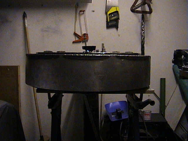
27/10/02 | Spot the difference between Mark I and Mark II. 25mm Lexan polycarbonate replaces the steel, which has now become a spare lid. We think were gonna need it. Bonus - 6kg lighter. |
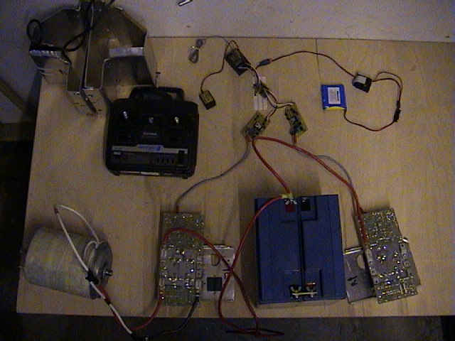  |
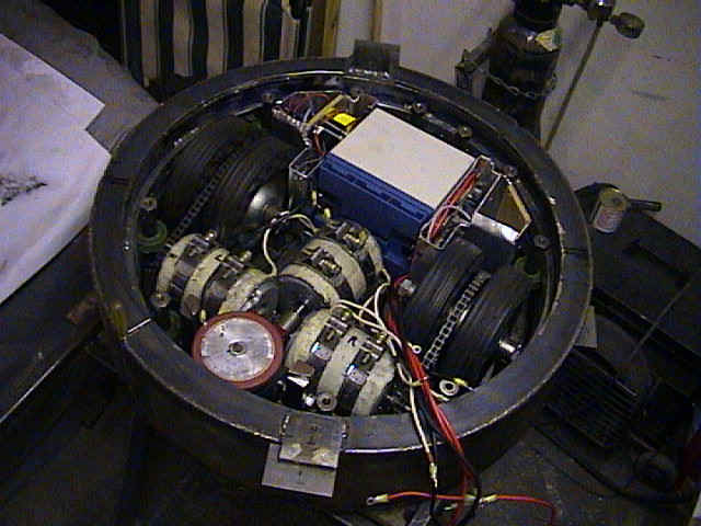
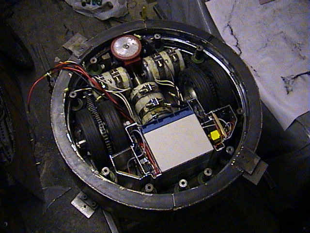
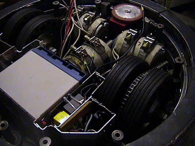
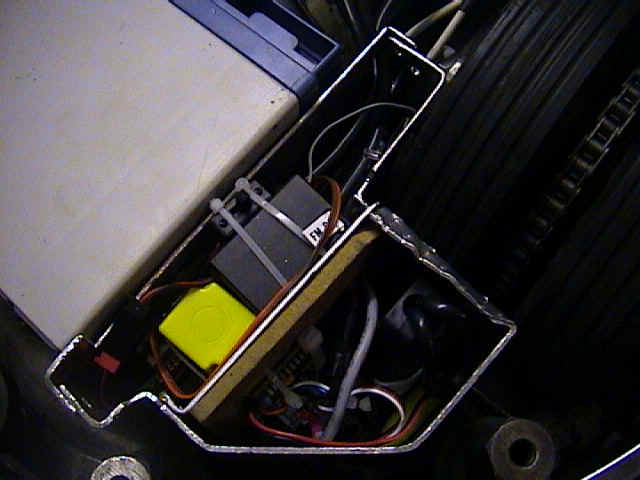
20/03/02 | Here are the drive electronics going through their bench test. Also, the chassis laid bare and painted in gold. All components are attached to what you see here. |
|
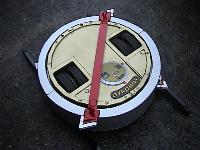
18/11/01 | Added interchangeable blades to allow for different styles of armour and
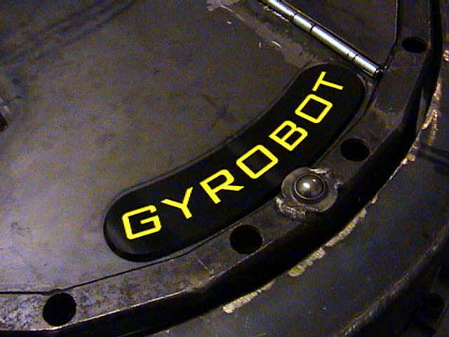
opponents. How small is that aerial? Anyone interested then contact www.quickuk.co.uk The third photo shows an almost finished Gyrobot bar the paint scheme, although when is any robot actually "finished"? Name plates have been NC machined from a bitmap supplied image. |
|
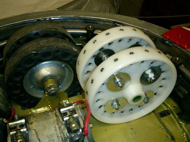
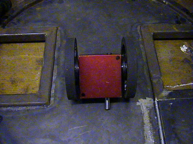
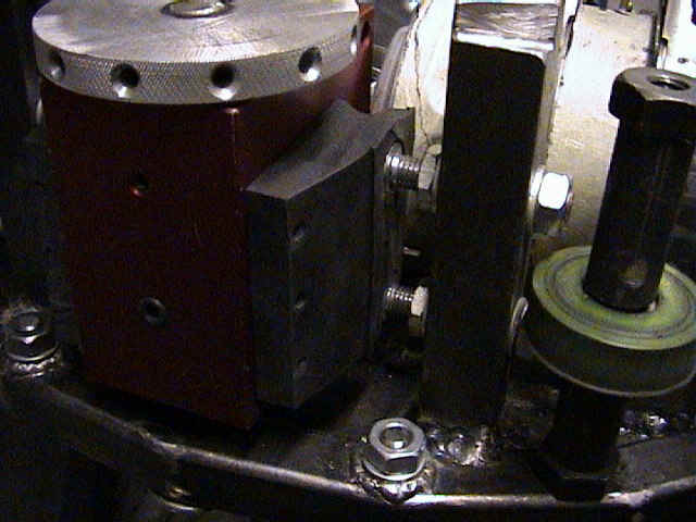
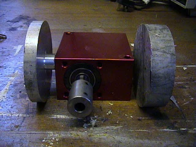
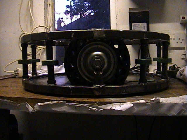
28/11/01 | New weapon drive gearbox now up together with tougher friction drive wheels. Just one of the enhancements incorporated for next years series. Testing of weapon drive spun the 35kg disk up to 400RPM in about 5 seconds. Add together the ability to spin the whole bot on the spot and we should have the potential to inflict massive amounts of damage. |
|
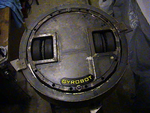
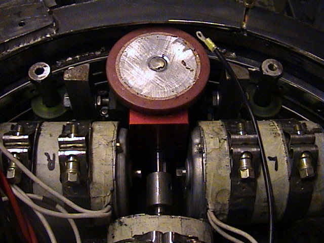
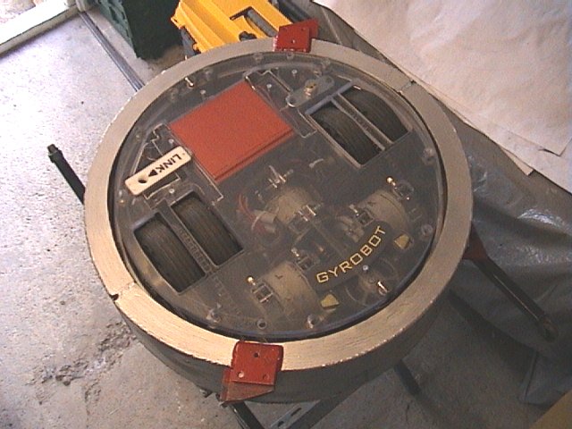
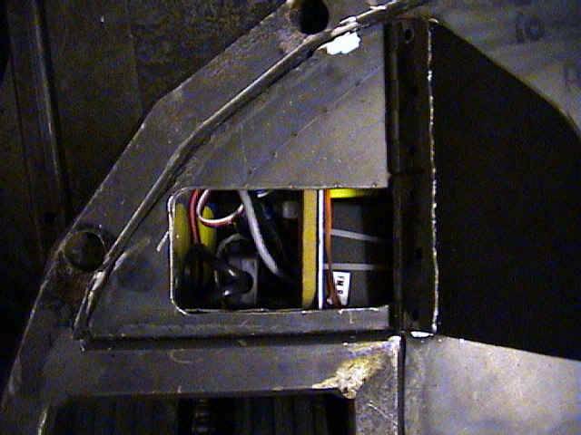
27/08/01 | Unfortunately we couldn't make the auditions for series 5 this year due to
unforseen last minute electrical problems. As you can see from the pictures on the left we
were not that far away, maybe another couple of weeks and it would have been a different
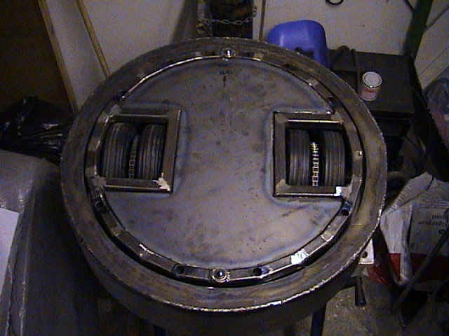
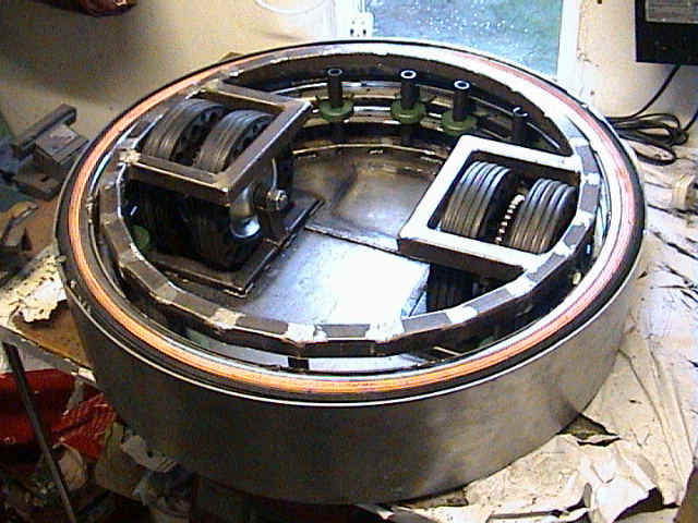
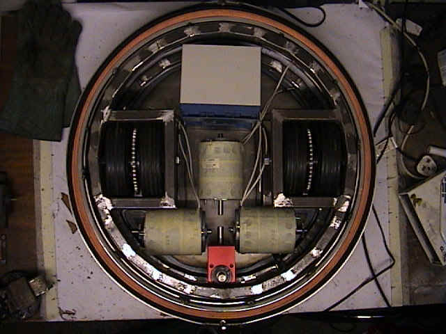
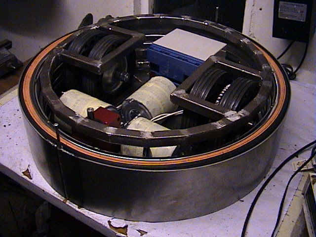
story. At least we should have lots of practice in by next year. Photos on the left show close ups of the access hole and cover door which allows entry to the removable link, RC crystals and on/off switch. Also shown are close ups of the electronic boxes and friction drive for spinning weapon. |
|
26/07/01 | A marathon photo fest!! Space is really getting tight now, skinning of
knuckles is an everyday occurance. Still, it is to be expected considering our boast of
being the smallest heavyweight. Dont think small means light, current weight is a whopping
95kg with the electronics still to add. A small price to pay due to the fact Gyrobot is
made of steel. Hover over pictures to get a description. |
|
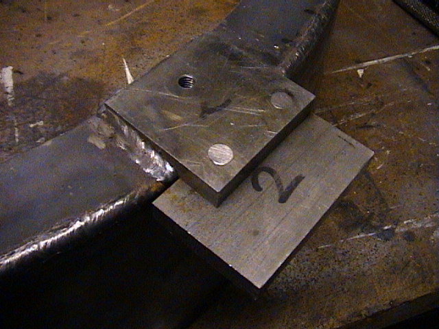
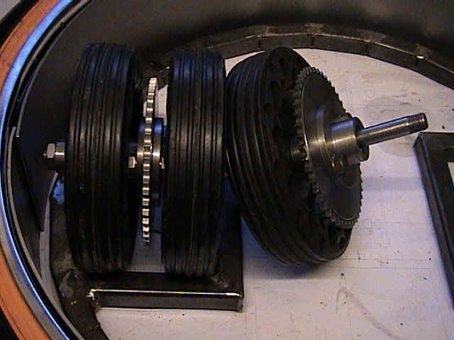
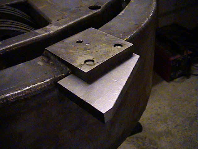
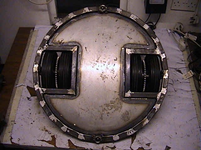
27/06/01 | Looks almost finished, but looks can be deceiving!! The last photo is a close up of what will become the weapon's drive wheels. Rubber will be moulded around the outside and the channels will allow the rubber to flow inside and lock into place. |
|
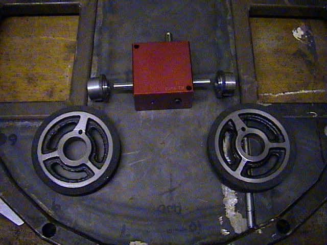
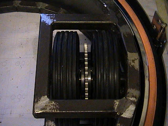
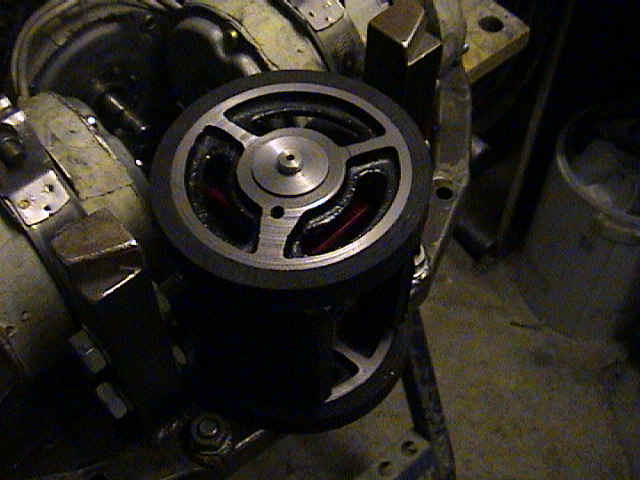
14/06/01 | A few random piccys. First one is of the weapon drive gearbox showing the
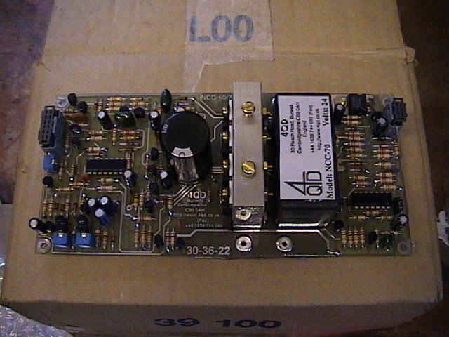
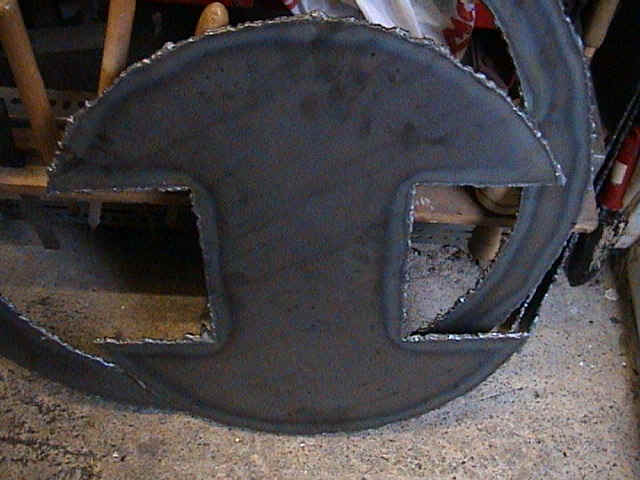
unfinished drive wheels. Second picture is showing the top armour plate burnt out of 4mm thick steel. Did we say 4mm, ooppps we ment to say 10mm, getting worried yet??? Ever wanted to know what a speed controller looked like, take a look at the third photo. This is 4QD's NCC-70 (See the links pages). |
|
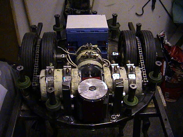
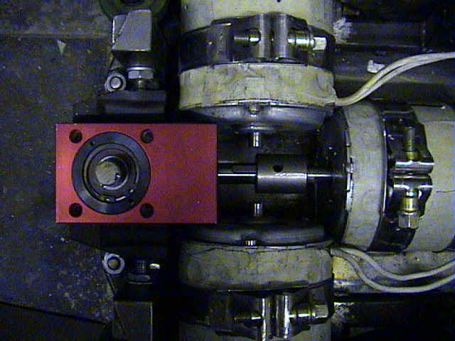
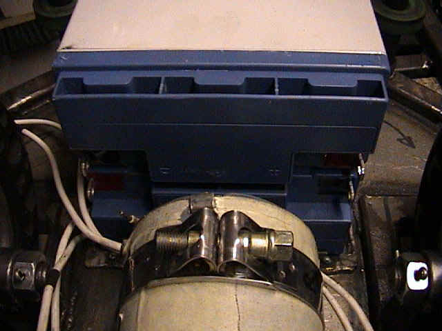
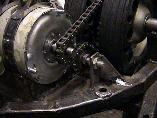
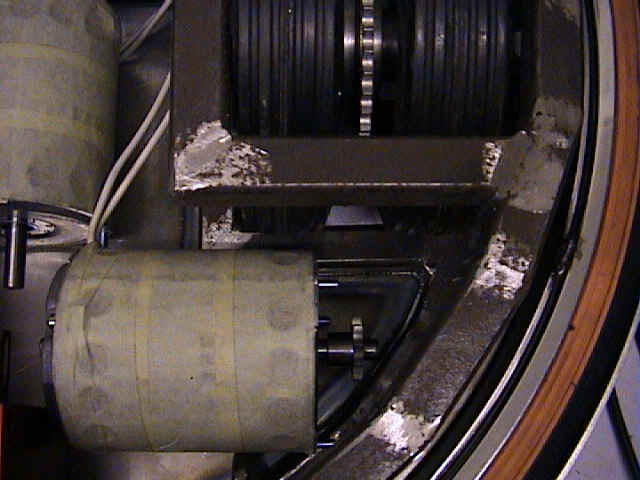
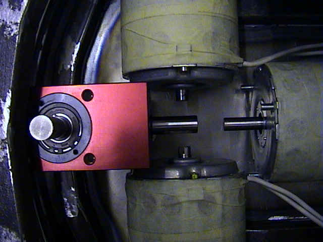
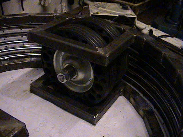
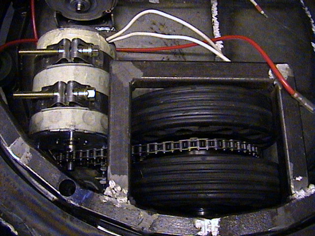
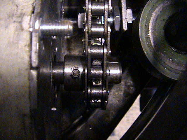
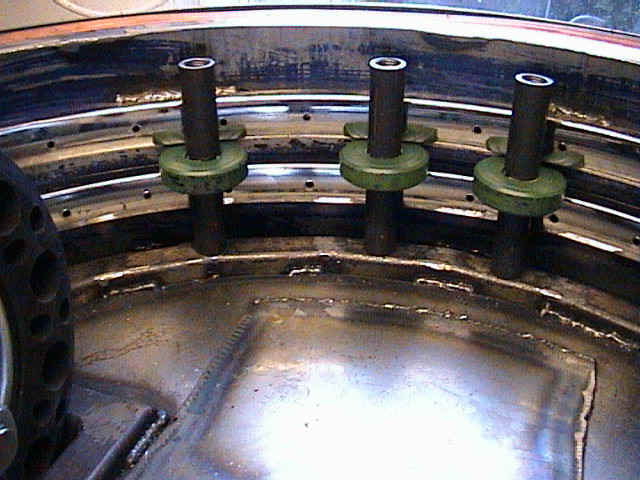
14/06/01 | Various views showing the Drive system. Sprocket on output shaft of motor
is pinned through shaft with a 4mm dia spring pin. A freewheeling chain tensioner shown in third picture (pillar removed) is to bend the chain sufficiently so that more teeth of the drive sprocket engage on to the chain. |
|
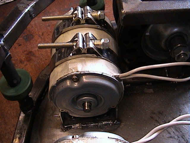
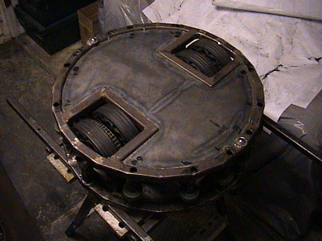
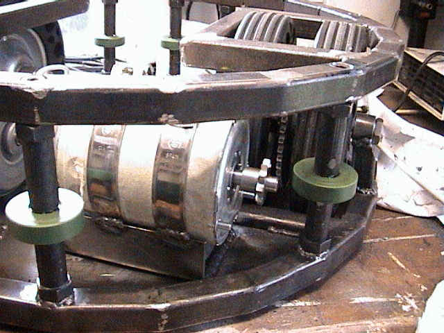
29/05/01 | Since the last entry, the drive motors have been mounted and clamped in
position. The clamps used are very high torque jubilee clips available from RS components
(See the links pages). The clips are then welded to a
"U" shaped piece of 3mm sheet steel, which doubles up as extra armour underneath
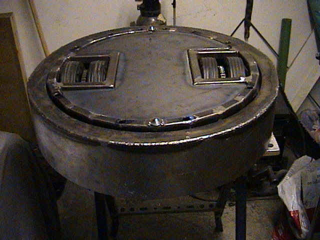
each motor. The weapon ring now has its top (or it's bottom??) cover added and seam welded all the way round. |
  |
22/05/01 | The rolling chassis is now finished. Now finally time to start mounting the internals. |
|
14/05/01 | After a couple of weeks of machining the chassis verticals, the weapon ring is finally attached and spinning. All be it using good old fashioned elbow grease, and not assisted by motors - yet. Oil filled nylon is the material used for the rollers, hard wearing and low frictional properties, we hope!!! |
|
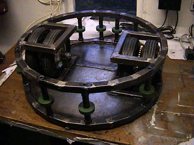
10/04/01 | Detailed photos of the lower half of the rolling chassis. Not to be used as a skateboard, It hurts when you fall off!! |
|
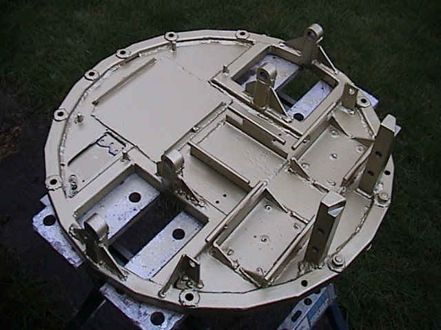
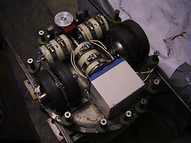
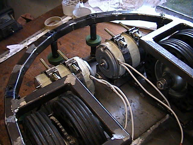
27/03/01 | The components are not attached at this stage but just placed in position, I couldn't resist taking a photo though. At least it looks something like the design. Don't forget to tape up the motors to stop iron filings and swarf getting too attached to the lovely big magnets inside. |
|
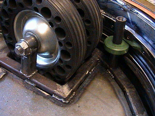
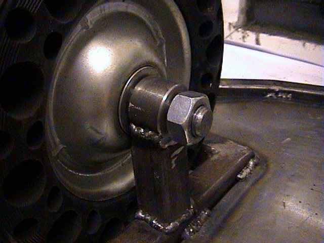
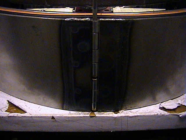
19/03/01 | Gives you an idea of the sort of armour we have. 3mm thick steel with
shock absorbing qualities due to the tyres underneath. The outer shell is removable and
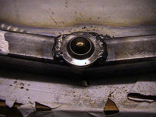
hinges away from the robot for maintenance to the shell and tyres underneath. Hinges can be seen in the second photo, again from 3mm thick steel. The third photo shows a more detailed breakdown of the wheel drive and spindle assembly. |
|
13/03/01 | Looking a bit like some sort mechanical device now. Still a long way to go though. All of the mumbo jumbo pictures shown below may make a bit more sense now - hopefully!! You can see the wheel drive and spindle assembly in the second and third photo. |
|
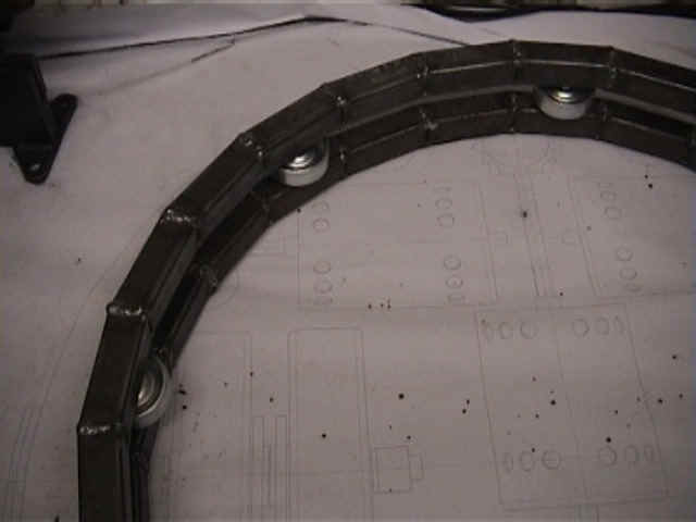
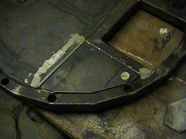
07/03/01 | One of the chassis rings shown with the wheel guards attached. |
|
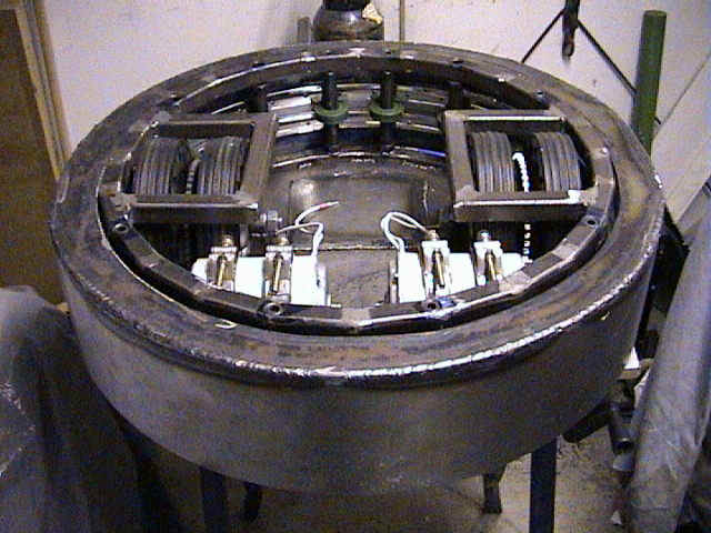
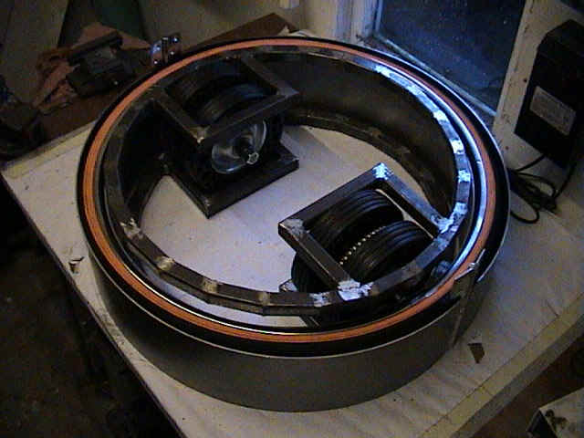
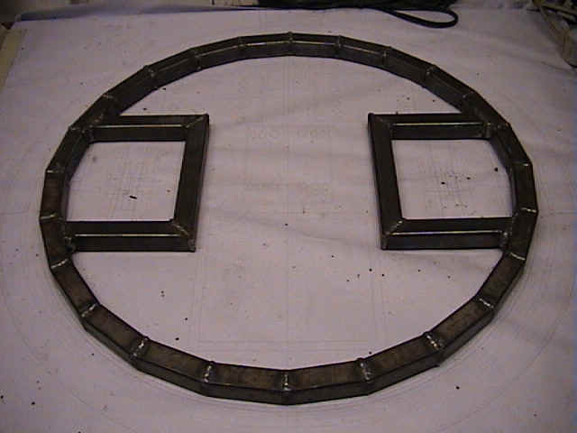
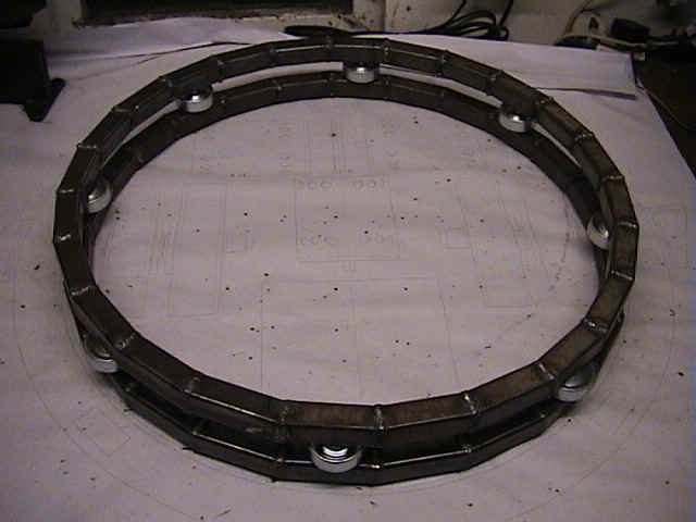
24/02/01 | The upper and lower chassis ring. Weapon rollers have been included just to give idea of the setup. The upper and lower rings will be further apart than shown, but we ran out of sky hooks so we can't show them in their actual position yet. |
|
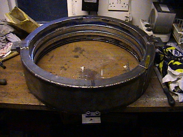
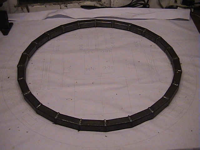
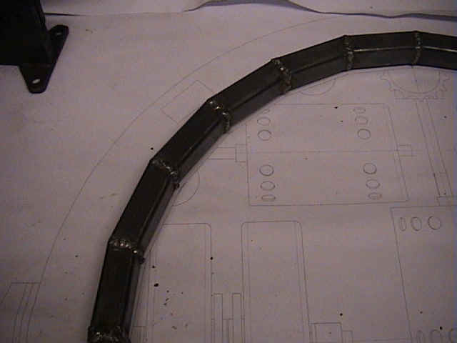
15/02/01 | Here we have the second Millenium Wheel!! Nah not really, it is the lower (or the top) inner chassis ring. Fabricated from 25mm square steel box tubing. It is positioned on a paper template of the design. |
|
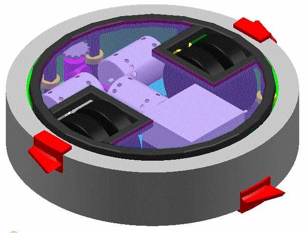
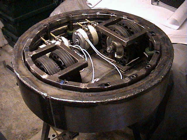
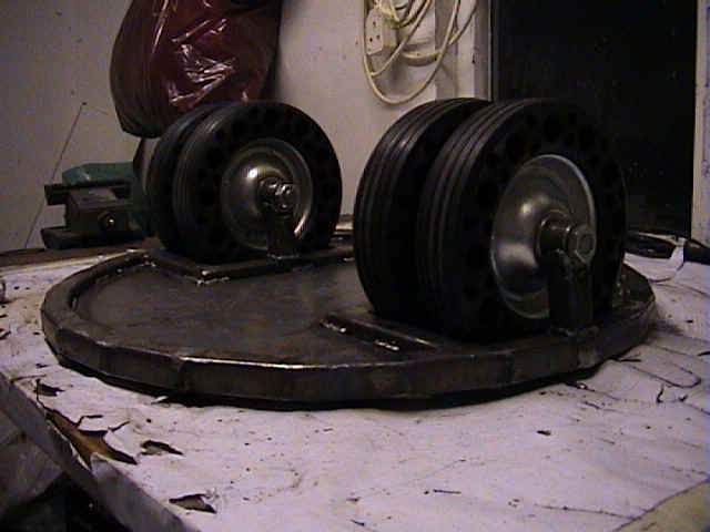
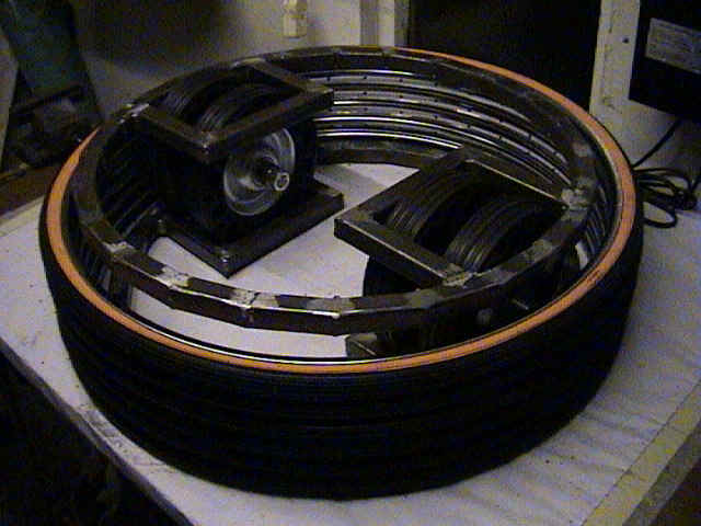
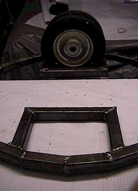
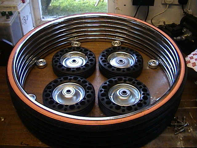
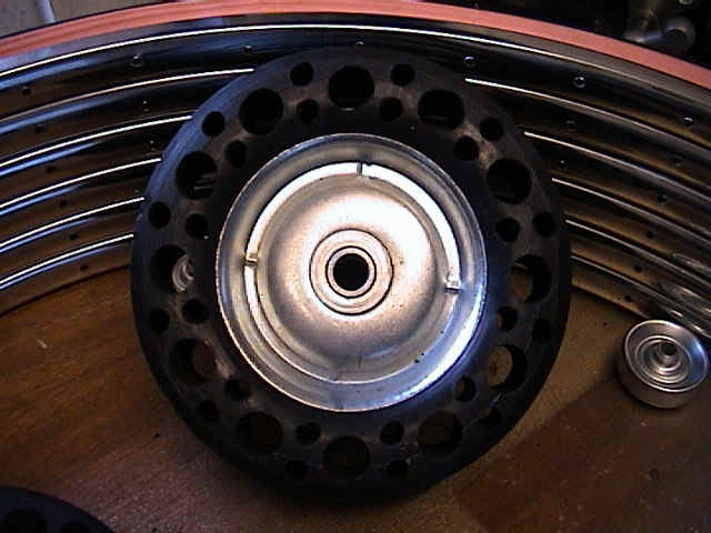
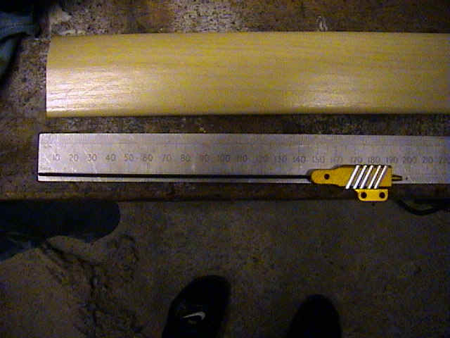
04/02/01 | Just to show you the scale of the weapon and the bot. The drive wheels are Dia 200mm. The eight castors shown are to allow the weapon ring to spin, and will be mounted halfway up the inner rim. |
|
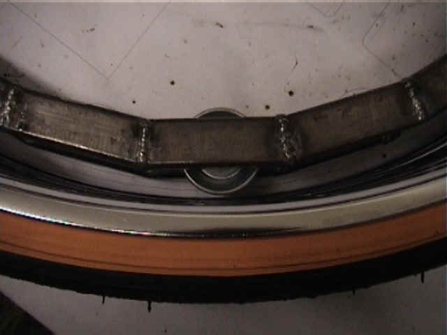
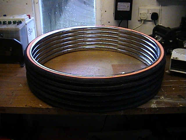
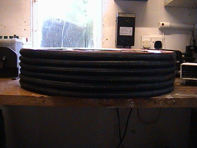
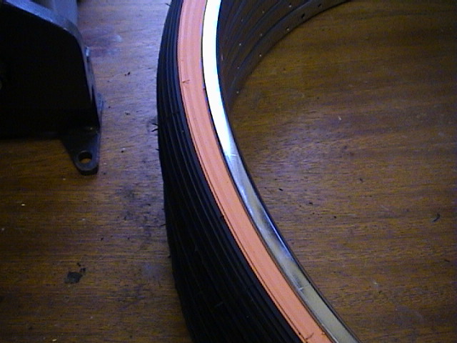
28/01/01 | This is the weapon's inner ring taking shape. Made from racing bike large wheel rims and tyres. Tyres will become shock absorbers after the outer weapon ring is assembled. |
|
"Gyrobot" - The robot and website is the creation of :-
"Plagiary is the lowest form of imagination but the highest compliment - HANDS OFF OUR BOTS" |